Radial Layout Mode
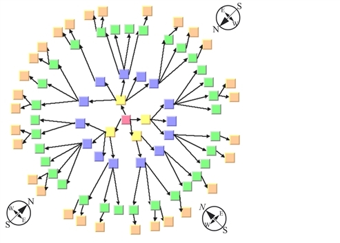
The radial layout mode partitions the node into levels and arranges the levels in circles around the root node. Radial Layout Mode shows an example of the radial layout mode. The compass icons show the compass directions in this drawing.
The following statement sets the radial layout mode:
layout->setLayoutMode(IlvTreeLayoutRadialMode);

The following statement sets the radial layout mode:
layout->setLayoutMode(IlvTreeLayoutRadialMode);
Additional parameter information for radial tree layout is as follows:
General Parameters
Most layout parameters that work for the free and level layout mode work as well for the radial layout mode. You can set the spacing offsets, the level justification, the global or individual link style, and the global or individual alignment. See
Here is a list of differences from the other modes:
-
The tip-over alignment does not work in radial layout mode.
-
The orthogonal link style does not work in radial mode.
-
The parent-child offset parameter controls the minimal distance between the circular levels. However, it is sometimes necessary to increase the offset between circular levels to obtain enough space on the circle to place all nodes of a level.
-
The level justification north means justification at the inner border of the circular level (that is, towards the root), and the level justification south means justification at the outer border of the circular level (that is, away from the root).
-
The level justifications north and south sometimes result in node overlapping.
-
The overlap percentage has no effect in radial layout mode.
Alternating Radial Mode
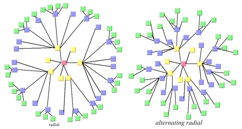
If levels contain many nodes, it is sometimes necessary to increase the radius of the circular level to provide enough space on the circumference of the circle for all the nodes. This may result in a considerable distance from the previous level. To avoid this, there is an alternating radial mode. This mode places the nodes of a level alternating onto two circles instead of one circle, resulting in a better space usage of the layout.
The alternating radial mode uses two circles only when necessary. For many small and light trees, there will be no difference from the normal radial mode. Only for large graphs with a high degree of children will the alternating radial mode have an effect.
The following statement sets the alternating radial layout mode:
layout->c(IlvTreeLayoutAlternatingRadialMode);

Radial and Alternating Radial Layout Mode
Aspect Ratio
If the drawing area is not a square, arranging levels as circles is not always the best choice. You can specify the aspect ratio of the drawing area to better fit the layout to the area. In this case, the algorithm uses ellipses instead of circles. See Sample Tree Layout in Radial Layout Mode with Aspect Ratio 1.3 for an example.
If the drawing area is a view (a subclass of IlvAbstractView), you can use this method:
void setAspectRatio(const IlvAbstractView* view);
If the drawing area is given only as a rectangle, use:
void setAspectRatio(const IlvRect& rect);
If neither a view nor a rectangle is given, you can calculate the aspect ratio from the width and height of the drawing area as aspectRatio = width/height and use this method:
void setAspectRatio(IlDouble aspectRatio);
To obtain the current aspect ratio, call:
IlDouble getAspectRatio() const;
Spacing Parameters
The spacing parameters of the radial layout mode are controlled by the same methods as for the free or level layout mode:
void setParentChildOffset(IlvPos offset);
void setSiblingOffset(IlvPos offset);
void setBranchOffset(IlvPos offset);
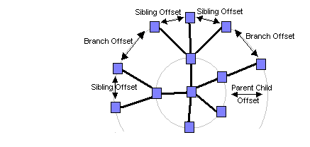
Note that the sibling and branch offsets are minimal distances tangential to the circles or ellipses, while the parent-child offset is a minimal distance radial to the circles or ellipses. Spacing Parameters in Radial Layout Mode shows the spacing parameters in radial mode.

Spacing Parameters in Radial Layout Mode
For Experts: Further Parameters
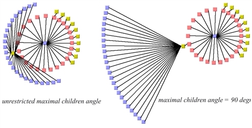
If a node has many children, they may cover a major part of the circle, and hence are placed nearly 360 degree around the node. This can result in links overlapping other nodes. The deficiency can be fixed by increasing the offset between parent and children. However, this influences the layout globally, also affecting nodes without the deficiency. To avoid a global change, you can limit the maximal angle between the two rays from the parent (if it is not the root) to its two outermost children. This increases the offset between parent and children only where necessary. Use the following method to set and obtain the angle in degrees:
void setMaxChildrenAngle(IlInt angle);
IlInt getMaxChildrenAngle() const;
Recommended values are between 30 and 180. Setting the value to 0 means the angle is unrestricted. The calculation of the angle is not very precise above 180 degrees, or if the aspect ratio is not 1.0.

Maximal Children Angle