Creating the Domain Nodes Panel
This section explains how to create the Domain Nodes panel of the Network application.
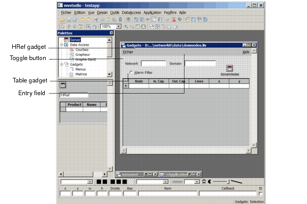
As you can see from the illustration below, this panel contains:

A table that represents the nodes of a given network domain with their input and output capacities, a hyper-reference to the Lines of Node panel, and two variables
x and
y that display the node coordinates. If you have a color monitor, you can see that nodes appear in different colors. The color of each node depends on the difference between its input capacity and its output capacity:
If its input capacity is greater than its output capacity, the node appears red and is in an alarm state.
If its output capacity exceeds its input capacity, the node appears blue.
When the load is balanced, the node takes a green color.
An entry field gadget that shows the name of the current domain.
A hyper-reference gadget (
HRef) that lets you activate the Network panel when you click on it.
An Alarm Filter toggle button to filter the nodes that are displayed in the table.
Figure 8.20 Final Domain Nodes Panel
When finished, this panel will look like this in the Main window:
Figure 8.21 Domain Nodes Panel in the Main Window
Following is the list of operations you are going to perform to create the Domain Nodes panel:
Create the
DomainNodes view,
Define the Main and Properties data sources related to the
DomainNodes view,
Fill in the data source table with values,
Add a parameter to the
DomainNodes view,
Create a hyper-reference to the Network panel,
Associate a gadget with the Properties data source,
Change a cell color according to a conditional expression,
Set the conditions for filtering a node.
Version 5.8
Copyright © 2014, Rogue Wave Software, Inc. All Rights Reserved.