Perforce JViews TGO Tutorial: Inventory Browser
Description
 |
This tutorial shows how to browse a network and equipment inventory database using Perforce JViews TGO.
How to Use the Tutorial
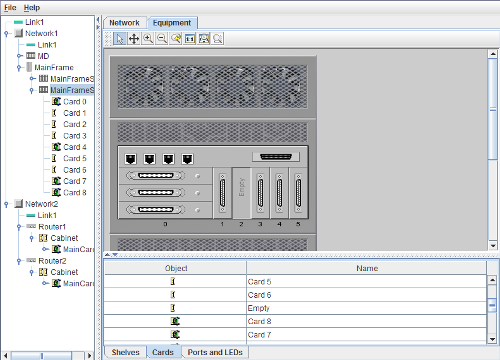
The tree shows the entire network hierarchy, from the root networks down to the details of ports and LEDs.
The main area is a tabbed pane with two tabs:
Shows one level of the network hierarchy.
Shows a detailed equipment view of one network element.
Contains a number of tables, each showing instances of a specific predefined business class. The tables are switched when the main area is toggled between network and equipment mode.
All the components show different views of the same data and they are synchronized. When you select an object in the tree, the corresponding object or its child objects are made visible and selected in the other components. For example, if you select Network 1 in the tree, the network view will be changed to show the elements contained in the network. You may achieve the same effect by double-clicking the network in the main area.
Now expand Network 1 in the tree and select one of the contained elements (for example, MainFrame). Note that the corresponding element is selected in the network. Switching to the equipment tab of the main area shows a detailed physical view of this element. Drill down even further in the tree to see the shelves, cards, ports, and LEDs that make up the network element. Any object that is selected in the tree will also be selected in the equipment area. Note that selecting a top-level object or a link will empty the equipment view, because there are no equipment details associated with these objects.
The contents of the tables are synchronized with the main area and they have the same selection. Selecting a different object in the main area will cause the selection in the table to change and vice versa. Since the objects of the main area are displayed in several tables, you may need to switch to a different table to see the selected object. For example, if you select one of the ports in the equipment area, you need to switch to the Ports and LEDs tab of the table area to see the corresponding table row. Selecting a different row there will also update the selection in the main view.
To return to the root network view, either select the top-level link (Link1) or right-click in the tree area outside any node to reset the selection.
How to Run the Tutorial as an Application
This tutorial can
be run as an application.
The installation directory contains
an executable JAR file,
tutorials-browser.jar,
that allows you to execute the tutorial with a double click from a
file browser. Note that if you are using Internet Explorer, you can
open the installation directory
and execute the JAR file from the browser. This
technique may not work in other Web browsers.
Alternatively, you
can run the tutorial application from the command line.
First check that the Ant utility is properly configured. If not, see the
instructions on how to configure Ant for Perforce JViews.
Then, go to the installation directory
of the tutorial and type:
ant run
Topics Covered
- Managing drill down with a tree and a network component
- Synchronizing selection between multiple components
- Reading network and equipment templates and substituting identifiers
Detailed Description
This tutorial focuses on the management of multiple levels of hierarchical data (implemented by the browser.DrillDownManager class) and the synchronization of selection between multiple graphic components (implemented by the browser.SelectionSynchronizer class).
All the data in this tutorial is loaded into a single data source, to which all the graphic components are connected. The tree displays the entire set of data; the other components show a subset only, either by manipulating the origins of their adapter (in the case of the network and equipment components) or by applying a filter (in the case of the tables).
Network and equipment templates
When the application is started, a file networks is loaded into the data source. This file contains the roots (two groups and a link) of the network. For each object that can contain a subnetwork, a template file is loaded into the data source using
DrillDownManager.loadTemplate. (In the tutorial we consider that only groups can have subnetworks, as implemented by the DrillDownManager.hasSubNetwork method.)
Similarly, an equipment template is loaded for each object that has equipment details. (See
DrillDownManager.hasEquipmentDetails.) The equipment templates (with names of the form <NE type>_equipment_template.xml) can be generated by the equipment editor.
The same template is typically shared by multiple instances of the network or network element. For example, there are two
Routers under Network2 and both have the same physical equipment hierarchy described in Router_equipment_template. However, the shelves, cards, ports, and LEDs contained under each router represent distinct Managed Objects in the underlying application. They are therefore associated with distinct business objects in the data source and must have a unique identifier. For this reason, the identifiers of the objects contained in the template file must be modified before the objects are inserted into the data source. This task is handled by passing an implementation of ilog.cpl.datasource.IlpIdentifierFactory to the ilog.cpl.storage.IlpDataSourceLoader that reads the template XML file. This factory will prepend the name of the parent object to the identifier found in the template, making it unique.
In addition to the business objects, each level of the network hierarchy may be associated with a configuration file, which is typically used to change the background of the network or equipment component and customize the representation of the objects. The configuration file is read at the same time as the template and applied on top of any existing configuration using the ilog.cpl.IlpNetwork.setStyleSheets and ilog.cpl.IlpEquipment.setStyleSheets methods for the network and equipment component respectively. An example of a configuration file is Mainframe_equipment_config. The style sheet is loaded when a subnetwork is being displayed using the DrillDownManager.showSubNetwork method. For the same reasons as outlined above for the business objects, the names of instances used in the selectors in the template must be modified to match the actual instances created in the data source. You can also define the representation of objects using selectors based on business classes, business attributes or model hierarchy, as illustrated in file MD_equipment_config.
Managing Drill-Down
All components are connected to a single data source that contains the entire network hierarchy. Each component (except the tree) shows only a subset of that data.
The network and equipment components select the data to show by manipulating the origins of their data source adapter. The adapter forms a bridge between the component and the data source, and it is created automatically when
setDataSource is called on the component.
The adapter can be retrieved using the
getAdapter() method. The origins of the adapter are modified by passing a list of ilog.cpl.model.IlpObject identifiers to the ilog.cpl.datasource.IlpAbstractHierarchyAdapter.setOrigins method. This method also takes a second parameter to indicate whether the origins themselves should be visible. This is usually set to false for network and equipment components, with one exception: passing an empty origin list and a true flag clears the contents of the entire component.
When drilling down in the network hierarchy, the table components at the bottom of the screen are updated to show only the objects currently visible in the main area. This is done by setting a new filter on each of the tables whenever a drill down occurs.
The createFilteredTable method of the browser.Main class creates an initial filter and then registers a listener to be notified whenever a drill down occurs, so that it can change the filter. The filter object is of class browser.OriginFilter, which accepts only objects that are the children of a given origin.
Synchronizing the Selection
To synchronize the selection between any number of components, browser.SelectionSynchronizer implements the listener interfaces for each of the graphic components: ilog.cpl.network.NetworkSelectionListener,
javax.swing.event.TreeSelectionListener and ilog.cpl.table.selection.TableSelectionListener. It then casts the source of the events of the selection to ilog.cpl.util.selection.IlpObjectSelectionModel, an interface that is implemented by each of the JTGO graphic component selection models. This permits the selection changes to be managed in a uniform way (see the processSelectionChange method).
Installation Directory
The Inventory Browser tutorial is installed here.
Classes Involved
-
ilog.cpl.IlpNetwork
The network component.
-
ilog.cpl.IlpEquipment
The equipment component.
-
ilog.cpl.IlpTree
The tree component.
-
ilog.cpl.IlpTable
The table component.
-
ilog.cpl.datasource.IlpIdentifierFactory
The factory that creates object identifiers when loading business objects from an XML file.
-
ilog.cpl.storage.IlpDataSourceLoader
The XML data source loader implementation.
-
ilog.cpl.datasource.IlpAbstractHierarchyAdapter
The adapter implementation shared by the network, equipment and tree components.
-
ilog.cpl.network.IlpNetworkSelectionModel
The network component selection model implementation.
-
ilog.cpl.tree.IlpTreeSelectionModel
The tree component selection model implementation.
-
ilog.cpl.table.selection.IlpTableSelectionModel
The table component selection model implementation.
-
ilog.cpl.util.selection.IlpObjectSelectionModel
The object component selection model implementation.
Source Files
-
browser.Main
The entry point of the tutorial.
-
browser.SelectionSynchronizer
The synchronization mechanism for selection models from different components.
-
browser.DrillDownManager
The component that handles drill down in the network and equipment components.
-
browser.OriginFilter
The filter that specifies the objects that shall be visible in the table according to the Network and Equipment component origins.