Perforce JViews TGO Sample: Network Component - Link Ports
Description
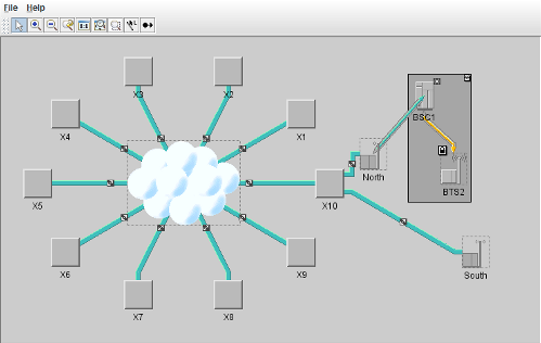 |
This sample shows how to use link connection ports.
How to Use the Sample
When the Edit link port interactor is enabled:
If the position is at the border of the node, the link connection port will have one of the directions Top, Bottom, Left, or Right.
If the position is inside the node, the link connection port will have no specific direction, that is, the links will come in from any direction.
data/linkPort_output.css) is generated with the current link port information.
How to Run the Sample as an Application
This sample can
be run as an application.
The installation directory contains
an executable JAR file,
network-linkPorts.jar,
that allows you to execute the sample with a double click from a
file browser. Note that if you are using Internet Explorer, you can
open the installation directory
and execute the JAR file from the browser. This
technique may not work in other Web browsers.
Alternatively, you
can run the sample application from the command line.
First check that the Ant utility is properly configured. If not, see the
instructions on how to configure Ant for Perforce JViews.
Then, go to the installation directory
of the sample and type:
ant run
Topics Covered
- Basic initialization
See thenetwork/basicsample for details. - How to constrain all links ending on a particular node
- How to constrain a particular link
- Using the ilog.tgo.interactor.IltEditLinkPortInteractor to let the user constrain links
- Using the ilog.cpl.css.IlpMutableStyleSheet to change the component configuration
Detailed Description
This sample demonstrates how to use link connection ports (pins). The specific code of this sample can be found in the doSample method of linkPorts.Main. The sample includes the following steps:
- Initialize the application using the method ilog.tgo.IltSystem.Init.
You pass the name of a deployment descriptor file to this method. - Create two link connection ports using the class ilog.tgo.graphic.IltLinkPort.
The names of the ports areRightAboveMiddleandRightBelowMiddle. - Create a standard data source of class ilog.tgo.datasource.IltDefaultDataSource.
- Create a network component of class ilog.cpl.IlpNetwork.
- Configure the network component using CSS files.
The network component configuration is separated into view and adapter configuration. The network adapter configuration handles the expansion of the subnetwork objects.
The network view configuration handles the toolbar, zoom policy and background configuration, among others. The network view configuration shows the following features:- Customizing the network view.
- Creating a custom button in the network component toolbar.
- Setting some properties on the graph layout installed through the CSS Network Configuration file (network).
- Customizing the network zoom policy.
- Attach the network component to the data source using the ilog.cpl.IlpNetwork.setDataSource method.
- Read a data file into the data source.
The data file network is read using the ilog.cpl.datasource.IlpDefaultDataSource.parse method. The file contains instances of some JTGO predefined classes: network elements, links. In this file, two links are constrained: the link going from nodeX10to nodeNorth, and the link going from nodeX10to nodeSouth.
To constrain a link, you use two attributes: - Add the network to your Swing application.
IlpNetworkis a SwingJComponent, which means that it can be added to your application like any other Swing component.
The class linkPorts.EditPinButton illustrates how you create new buttons to the Network component toolbar. This class includes the following steps:
- Implement a network toolbar button.
In order to be able to add the toolbar button using style sheets, this class must implement a constructor that takes an ilog.cpl.graphic.views.IlpViewsView parameter. In this constructor, you specify the action that will be performed when the button is activated, as well as the configuration used to display the button in the toolbar. You can also specify properties that can be customized using style sheets, for instance, propertyfreeModeis declared in this sample to allow the customization of the edit link port interactor mode. - Implement a network interactor action (ilog.cpl.network.action.toolbar.IlpNetworkInteractorAction).
This action is associated to a view interactor. When the action is performed, the view interactor is attached to the associated view. - Implement an extension of the edit link port interactor (ilog.tgo.interactor.IltEditLinkPortInteractor)
This interactor implementation overrides methods that are used to indicate which mutable style sheet will be used by the view to store the changes in the link ports (seegetStyleSheet,attachStyleSheetanddetachStyleSheetmethods). In this sample, methoddetachStyleSheetalso dumps the link port configuration to an output file.
Installation Directory
The Network Component - Link Ports sample is installed here.
Classes Involved
-
ilog.tgo.IltSystem
The class that initializes a JViews TGO application.
-
ilog.tgo.datasource.IltDefaultDataSource
The default datasource implementation.
-
ilog.cpl.IlpNetwork
The network component.
-
ilog.tgo.graphic.IltLinkPort
The link port implementation.
-
ilog.tgo.interactor.IltEditLinkPortInteractor
The link port edit interactor.
-
ilog.cpl.css.IlpMutableStyleSheet
The mutable style sheet implementation.
-
ilog.cpl.network.action.toolbar.IlpNetworkInteractorAction
The action to associate interactors to toolbar buttons.
-
ilog.cpl.network.action.toolbar.IlpNetworkInteractorButton
The network interactor toolbar button.
-
ilog.tgo.graphic.graphlayout.IltShortLinkLayout
The link layout that supports link ports.
-
ilog.tgo.model.IltAbstractLink
The link business object.
-
ilog.cpl.graphic.views.IlpViewsView
The graphic view which uses a Perforce JViews
IlvManagerViewobject for displaying.
Source Files
-
linkPorts.Main
The entry point of the sample.
-
linkPorts.EditPinButton
The toolbar button to the edit link port interactor