Rogue Wave JViews TGO Sample: Network Component - Topological Layout
Description
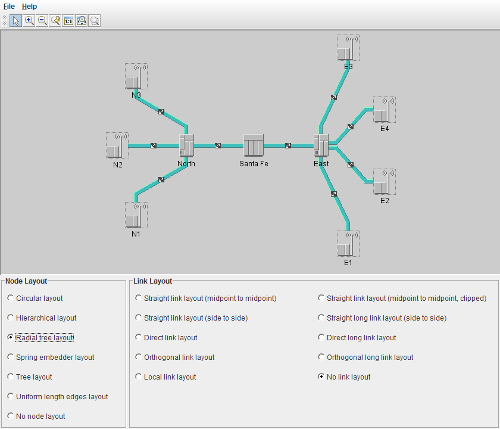 |
This sample shows how to use the Node and the Link graph layouts in a JViews TGO network component to create topological views.
How to Use the Sample
The main view contains a basic network component with a series of links and network elements. The bottom control panel contains the controls used to configure the node and link layouts of the network.
You can select the various combinations of node and link layouts to compose a topological view.
Note: You are only allowed to move the nodes when there is no node layout set on the network.
How to Run the Sample as an Application
This sample can also be run as an application. The installation directory contains an executable JAR file, network-topologicalLayout.jar, that allows you to execute the sample with a double click from a file browser. Note that if you are using Internet Explorer, you can open the installation directory and execute the JAR file from the browser. This technique may not work in other Web browsers.
Alternatively, you can run the sample application from the command line. First check that the Ant utility is properly configured. If not, see the instructions on how to configure Ant for Rogue Wave JViews.
Then, go to the installation directory of the sample and type:
ant run
Topics Covered
- Creating a network component
- Creating objects and adding them to the data source using XML
- Configuring node layouts using CSS
- Configuring link layout using the API
Detailed Description
This sample shows how to use the node and link graph layouts to create topological views. This is generally done through the following steps:
- Create the
IlvGraphLayoutsubclass object that you would like to use as either your node or your link layout. - Depending on the
IlvGraphLayoutsubclass, you may have to configure the layout by setting some layout parameters. - Attach the subclass to the network view or to the network itself by using one of the methods
setGraphLayouts,setNodeLayout, orsetLinkLayout. See the following classes for other options:
In this sample, the data source business objects as well as the network component configuration are loaded as part of a project configuration file. When the project file is set, the following steps are performed:
- The configuration files are applied to the component.
- A data source is created according to the class specified in the project configuration. In this case, it creates a standard data source of class ilog.tgo.datasource.IltDefaultDataSource.
- The data file network, which contains predefined JTGO classes (business objects), is read.
- Finally, the data source is attached to the network component.
The component configuration can also be specified in the network component constructor or later, through the method ilog.cpl.IlpNetwork.setStyleSheets, you can pass the name of a configuration file (network).
In this sample, besides the usual configuration, the component configuration file also illustrates how you can configure non-automatic multiple node layouts. This configuration can be verified in the GraphLayout rule present in file network. In this rule, the different graph layouts are created and set using the layouts property. As they should be performed when you select the node layout in the application panel, none of these layouts is selected to be executed automatically. To indicate this, property autoLayoutIndex is set to -1. The component configuration file also illustrates how you can customize per-object layout parameters for circular and tree layouts.
Installation Directory
The Network Component - Topological Layout sample is installed here.
Classes Involved
-
ilog.tgo.IltSystem
The class that initializes a JViews TGO application.
-
ilog.cpl.IlpNetwork
The network component.
-
ilog.cpl.network.IlpNetworkView
The network view implementation.
-
ilog.cpl.network.renderer.IlpGraphLayoutRenderer
The renderer for graph layout CSS configuration.
-
ilog.views.graphlayout.circular.IlvCircularLayout
The circular layout implementation.
-
ilog.views.graphlayout.hierarchical.IlvHierarchicalLayout
The hierarchical layout implementation.
-
ilog.views.graphlayout.tree.IlvTreeLayout
The tree layout implementation.
-
ilog.views.graphlayout.springembedder.IlvSpringEmbedderLayout
The spring embedder layout implementation.
-
ilog.views.graphlayout.uniformlengthedges.IlvUniformLengthEdgesLayout
The uniform length edges layout implementation.
-
ilog.views.graphlayout.link.IlvLinkLayout
The link layout implementation.
-
ilog.tgo.graphic.graphlayout.IltStraightLinkLayout
The straight link layout implementation.
-
ilog.tgo.graphic.graphlayout.IltLocalLinkLayout
The local link layout implementation.
-
ilog.tgo.datasource.IltDefaultDataSource
The default data source implementation.
Source Files
-
topologicalLayout.Main
The entry point of the sample.