Rogue Wave JViews TGO Sample: Network Component - Bus Layout
Description
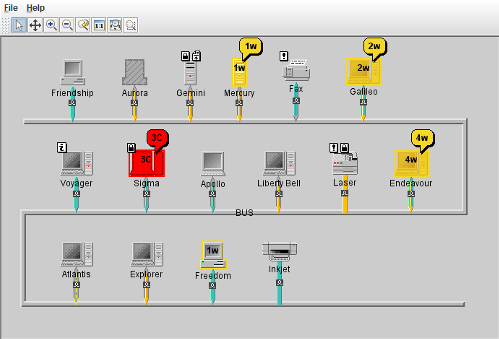 |
This sample shows how to use the bus layout features with the Rogue Wave JViews TGO network component.
How to Use the Sample
The main frame contains a simple network component, with several different types of network elements and links connected to a bus object. It illustrates how to use the bus layout with a JTGO network component.
A network component has a default toolbar which provides a set of predefined interactors:
- Select
- Pan
- Reset Zoom
- Zoom In
- Zoom Out
- Zoom Back
- Fit to Contents
- Zoom on a Rectangle
How to Run the Sample as an Application
This sample can also be run as an application. The installation directory contains an executable JAR file, network-busLayout.jar, that allows you to execute the sample with a double click from a file browser. Note that if you are using Internet Explorer, you can open the installation directory and execute the JAR file from the browser. This technique may not work in other Web browsers.
Alternatively, you can run the sample application from the command line. First check that the Ant utility is properly configured. If not, see the instructions on how to configure Ant for Rogue Wave JViews.
Then, go to the installation directory of the sample and type:
ant run
Topics Covered
- Initializing a JTGO application using a deployment descriptor
- Creating a data source
- Creating a network component and configuring it using a CSS configuration file
- Associating the data source with the network component
- Reading data from an XML file into the data source
- Configuring the bus layout to be used with the JTGO network component
Detailed Description
This sample shows how to create a network component and configure it to display its objects positioned according to a bus layout configuration.
Bus topology is well known in network management and telecommunications fields. The Bus Layout can display these topologies nicely. It represents the "bus" as a "serpent" polyline. The width of the "serpent" is user-defined (via the width of the layout region parameter) and the height is computed so that enough space is available for all the nodes.
The Bus Layout places the nodes and reshapes the links, so that it is usually not necessary to specify an additional link layout to the network component. In order to have the business objects correctly laid out by the Bus Layout, the data source that is connected to the network component needs to contain a bus node connected with links to several other nodes. When you specify the Bus Layout in CSS, the data model must respect this condition.
In JTGO, the bus node is represented by an ilog.tgo.model.IltLinearGroup. The linear group object is added to the data source with a generic position. There are two steps to perform in the linear group configuration so that it can be used as a bus node by the layout:
- The bus layout property bus must be configured in the component configuration indicating which object will be the bus for the layout. This is achieved as follows:
#BUS:graphLayoutRenderer:bus {
  bus: true;
}
The Rogue Wave JViews layout algorithms provide many parameters that control how a specific layout will be applied to a particular node or link. These parameters can be configured using CSS. In the example above, the declaration bus will cause the method ilog.views.graphlayout.bus.IlvBusLayout.setBus to be called for the node that matches the rule. To set a per-object property for a graph layout, you have to identify the selector using the pseudoclassgraphLayoutRendererorlinkLayoutRenderer, depending if the property is a graph layout or link layout property, and the pseudoclass that identifies the graph layout that is being customized. - The linear group must have property
linksConnectToBaseset totruein the component configuration, as illustrated below:#BUS { linksConnectToBase: true; }
The code of this sample can be found in the doSample method.
To create a network component, the sample includes the following steps:
- Initialize the application using the method ilog.tgo.IltSystem.Init. You can pass a deployment descriptor file to this method. This file contains information about global settings for the application.
In this sample, the descriptor is called deploy and contains directories to be added to the search path.
These directories are necessary to locate:- images in the
resourcesdirectory, - the data source file and the network configuration files in the
datadirectory.
- images in the
- Create a standard data source of class ilog.tgo.datasource.IltDefaultDataSource.
- Create a network component and load its configuration from a CSS file.
The network component is of class ilog.cpl.IlpNetwork. In its constructor, or later through the method ilog.cpl.IlpNetwork.setStyleSheets, you pass the name of a configuration file (network) which describes the:
- Buttons to add to the toolbar
For a list of available buttons, see the ilog.cpl.network.renderer.IlpToolBarRenderer class.
- Default interactor to use
This should be the name of one of the buttons of the toolbar.
- View configuration
For a list of available properties, see the ilog.cpl.network.renderer.IlpViewRenderer class.
- Graph layout configuration
For a list of available properties, see the ilog.cpl.network.renderer.IlpGraphLayoutRenderer.
In this sample, we illustrate the use of a bus layout. (See the ilog.views.graphlayout.bus.IlvBusLayout class) - Object representation properties
- Buttons to add to the toolbar
- Attach the network component to the data source.
Use the ilog.cpl.IlpNetwork.setDataSource method.
- Read a data file containing the definition of the bus topology.
The data file network is read using the ilog.cpl.datasource.IlpDefaultDataSource.parse method. It contains instances of some JTGO predefined classes: linear group, network elements and links.
- Add the network to your Swing application.
IlpNetworkis a SwingJComponent, which means that it can be added to your application like any other Swing component.
Installation Directory
The Network Component - Bus Layout sample is installed here.
Classes Involved
-
ilog.tgo.IltSystem
The class that initializes a JViews TGO application.
-
ilog.tgo.datasource.IltDefaultDataSource
The default datasource implementation.
-
ilog.cpl.IlpNetwork
The network component.
-
ilog.cpl.network.IlpNetworkView
The network view implementation.
-
ilog.cpl.network.IlpNetworkAdapter
The network adapter implementation.
-
ilog.views.graphlayout.bus.IlvBusLayout
The bus layout implementation.
-
ilog.tgo.model.IltLinearGroup
The linear group business object.
-
ilog.cpl.network.renderer.IlpToolBarRenderer
This class gives control over the toolbar of a network component.
-
ilog.cpl.network.renderer.IlpViewRenderer
This class gives control over the view of a network component.
-
ilog.cpl.network.renderer.IlpGraphLayoutRenderer
This class gives control over the graph layout of a network component.
Source Files
-
busLayout.Main
The entry point of the sample.
-
busLayout.IncrementalBusLayout
The incremental bus layout implementation.