Rogue Wave JViews TGO Sample: Equipment Component - Editor
Description
 |
The Equipment Editor allows you to generate an equipment view through drag-and-drop graphical interactions.
How to Use the Sample
This section shows you how to: Each task is explained in more detail below:
equipmenteditor sample.
The equipment editor opens with a new empty buffer view.
slotSizes value in the Attribute column (here the value is 5x1, but it may vary with the shelf). The editor window opens:

A grid displays in the buffer view.
The shelf snaps to the grid. This setting enables you to align objects with accuracy.
The grid disappears from the buffer view.
This setting enables you to position objects with accuracy.
The possible values depend on the underlying shelf. They may be less than 1 when a card does not occupy a whole slot.
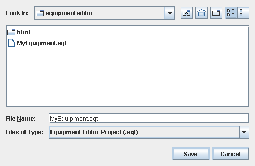
myEquipment or myEquipment.eqt and click OK.
Three files are created: myEquipment.eqt (a kind of project file pointing to the other two files), myEquipment_template.xml (containing the equipment data), and myEquipment_config.css (containing the configuration of the equipment, for example the background used).
This section shows you how to edit an existing equipment file.
equipmenteditor sample.
The equipment editor opens with a new empty buffer view.
myEquipment.eqt that you created previously.
The file chooser shows a preview of the selected equipment.
type attribute and select another port.type attribute and select another LED.
By doing so, you loose the spanning you have specified for this card.
myEquipment2 or myEquipment2.eqt and click OK.
How to Run the Sample as an Application
This sample can
be run as an application.
The installation directory contains
an executable JAR file,
equipment-editor.jar,
that allows you to execute the sample with a double click from a
file browser. Note that if you are using Internet Explorer, you can
open the installation directory
and execute the JAR file from the browser. This
technique may not work in other Web browsers.
Alternatively, you
can run the sample application from the command line.
First check that the Ant utility is properly configured. If not, see the
instructions on how to configure Ant for Rogue Wave JViews.
Then, go to the installation directory
of the sample and type:
ant run
Topics Covered
- Initializing a JTGO application
- Creating an equipment component
- Creating shelves and card carriers
- Creating cards
- Creating ports and LEDs
- Creating equipment templates by drag-and-drop
Detailed Description
The graphical user interface of the Equipment Editor as supplied in Rogue Wave JViews TGO is made up of the following elements:
- A menu bar
- A toolbar
- A buffer view with its own toolbar. This view displays the equipment you are building or editing.
- A set of tabbed panes which allows you to switch between palettes of equipment objects and a tree view showing the hierarchy of objects which make up the equipment in the buffer view.
- An area at the bottom left of the editor where you can change the attribute values or the identifier of the selected object.
The Equipment Editor Menu Bar
The menu bar includes the File, Edit, View, Background, Palette, Window and Help menus. Some of the commands of these menus can be accessed through the toolbars. You can access the menu commands either with the mouse or by using a keyboard shortcut. The appropriate key sequence is shown beside each menu option.
File Menu
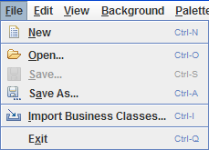
The file menu contains the following commands:
- New (Ctrl-N) opens a new buffer view to build new equipment.
-
Open (Ctrl-O) allows you to load an equipment from an Equipment Editor file (
.eqt) or from an XML file, in the active buffer view. -
Save (Ctrl-S) saves the contents of the active buffer view in an Equipment Editor file (
.eqt) or in an XML file. -
Save As (Ctrl-A) saves the contents of the active buffer view in an Equipment Editor file (
.eqt) or in an XML file. - Import Business Classes (Ctrl-I) allows you to import business classes from an XML business classes file in order to create custom business objects. The business classes must be compatible with the classes supported by the equipment component. In other words, these classes must be an extension of the supported classes.
- Exit (Ctrl-Q) quits the application.
Edit Menu
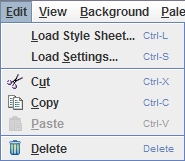
The Edit menu contains the following commands:
- Load Style Sheet (Ctrl-L) allows you to apply styling to the equipment in the buffer view by loading a style sheet.
-
Load Settings (Ctrl-S) allows you to load a CSS file that contains JViews TGO settings. Ensure to add to the
Manafest.mf's classpath any JAR files that contain any classes this settings file may reference. Also if the settings file references resources such as other CSS files or images, ensure to add their paths to the Equipment Editor'sdeploy.xmlso that these resources can be found. - Cut (Ctrl-X) removes the selected objects from the active buffer view.
- Copy (Ctrl-C) makes a copy of the selected objects in the active buffer view.
- Paste (Ctrl-V) pastes the objects you have previously cut or copied and places them in the active buffer view.
- Delete removes the selected objects from the active buffer view.
View Menu
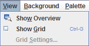
The View menu contains the following commands:
- Show Overview displays an overview of the contents of the active buffer view.
- Show Grid (Ctrl-G) displays a grid in the active buffer view. The grid helps you accurately align the objects in the buffer view. A check mark in front of the command means that the grid is displayed.
- Grid Settings allows you to change the horizontal and vertical spacing of the grid dots, as well as the horizontal and vertical origin of the grid dots. This command also enables you to activate or deactivate snapping to the grid.
Background Menu
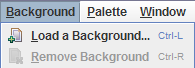
The Background menu contains the following commands:
- Load a Background (Ctrl-L) allows you to select a background for the active buffer.
- Remove Background (Ctrl-R) allows you to remove the background set for the active buffer.
Each equipment buffer view can have a background loaded or removed through the Background menu.
Palette Menu
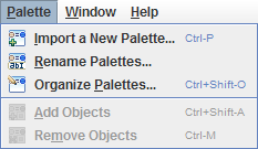
The Palette menu contains the following commands:
- Import a New Palette (Ctrl-P) allows you to import a palette and add it to the current set of palettes.
- Rename Palettes allows you to rename the available palettes.
- Organize Palettes (Ctrl-Shift-O) allows you to add or remove palettes to or from the palette view.
- Add Objects (Ctrl-Shift-A) allows you to add selected objects from the active buffer view to the active palette (except to the default palettes).
- Remove Objects (Ctrl-M) allows you to remove selected objects from the active palette (except from the default palettes).
Window Menu
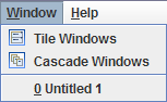
The Window menu contains the following commands:
- Tile Windows displays the buffer views in tiles, side by side.
- Cascade Windows displays the buffer views in a cascade, one view below the other with a slight offset. Below the separator, the open buffer views that you can bring to the foreground are listed.
- Untitled brings the corresponding open buffer view to the foreground.
Help Menu

The Help menu contains the following commands:
- About displays information about the current version of the editor.
The Equipment Editor Toolbar
The main toolbar is displayed at the top of the editor, below the menu bar. It is dockable, which means that you can detach it by dragging and dropping (point at the left border of the toolbar to drag it).

The toolbar provides shortcut buttons for the following menu commands:
- Create a New buffer view.
- Open a file in the active buffer view.
-
Save the contents of the active buffer view in an equipment editor file (
.eqt) or in a XML file. - Cut the selected objects from the active buffer view.
- Copy the selected objects in the active buffer.
- Paste the selected objects and place them in the active buffer view.
- Delete the selected objects from the active buffer view.
- Show an overview window allowing you to adjust the visible part of the buffer view.
- Load a Background for the equipment in the active buffer view.
- Remove the Background of the equipment in the active buffer view.
- Organize Palettes by adding or removing them.
- Rename Palettes.
- Import a New Palette.
- Add Objects to a palette.
- Remove Objects from a palette.
The Equipment Editor Views
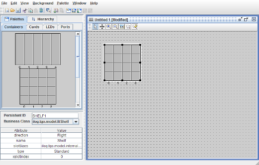
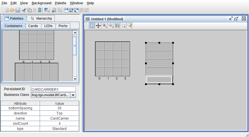
The Equipment Editor contains four views: a palettes view, a hierarchy view, an object attributes view, and a buffer view. The first two views display in the top left part of the editor, and can be switched by clicking the corresponding tabs. The object attributes view displays in the bottom left part of the editor. The buffer view displays in the right part; it is a floating window.
Palettes
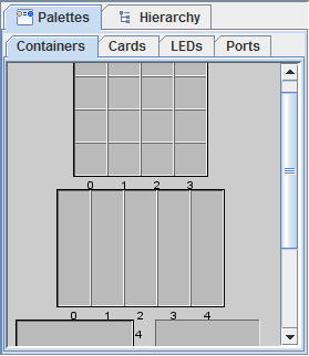
The Palettes tab itself contains four tabbed panes corresponding to the categories of objects that you can drag and drop into the buffer view to build your equipment. By default, there are four palettes: Containers (shelves, card carriers), Cards, Ports, and LEDs. You can create your own palettes, add them as new tabs or replace the default ones.
Click a tab to display the corresponding set of equipment objects. You can use any of these objects by simply dragging and dropping them into the buffer view.
Object Attributes
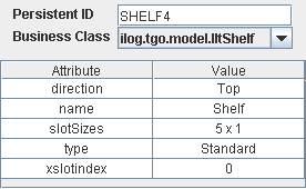
The bottom left part of the editor displays the identifier, type and attributes of the selected object.
The editor creates unique identifiers, but you can modify them to make the connection to a back-end application easier. To change the identifier of a selected object, enter the new identifier in the Persistent ID text box, and press Return. The new identifier will be saved with the buffer view.
The class of the selected object is indicated in the Business Class combo box. This combo box shows all the classes that are compatible with the selected object. To import custom business classes, you can either add your business class definitions to the deployment descriptor so that they are loaded when the Equipment Editor is launched, or you can import the class definitions dynamically through the menu item File->Import Business Classes. Once your business classes are available in the Equipment Editor, all objects created can have their classes changed.
The attributes of the selected object and their values display in a two-column table. When you change an attribute value, the selected object in the buffer view is automatically updated.
Hierarchy View
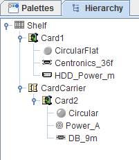
The hierarchy view displays the hierarchical structure of the equipment displayed in the active buffer view. An equipment is a potential container of several objects with different levels of embedding. This containment hierarchy is illustrated in the form of a tree.
The tree is a visual representation of the structure of the equipment in the buffer view. It displays the name of the objects with an icon representing their type. Among the icons are the following:
-
 represents a shelf.
 -
 represents a card carrier.
 -
 represents a card.
 - Ports and LEDs have their own representation based on the specific type.
The selection in the tree reflects the selection in the active buffer view.
Buffer View
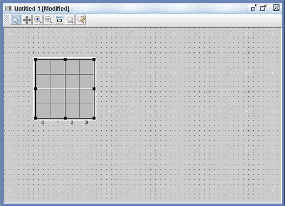
The buffer view is a floating window in which you model your equipment. This is actually your workspace. You can have several buffer views open at a time.
In a buffer view, you can:
- Drag and drop equipment objects from a palette
- Display a background
- Load an Equipment Editor file (
.eqt) or an XML file containing the description of an equipment - Select, move, resize equipment objects
- Cut, copy, paste equipment objects in the same buffer view or between several buffer views
The following set of interactors is associated with the buffer view.
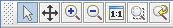
Click interactors (icons) in the toolbar to:
- Select, move and reshape objects in the active buffer view.
- Pan the active buffer view.
- Zoom in the active buffer view.
- Zoom out the active buffer view.
- Reset the view to the original zoom level.
- Zoom on a user-defined rectangular area.
- Zoom back to the last zoom level.
Equipment Editor Features
This section describes the following main features of the equipment editor:
Equipment objects
The objects you can use to build an equipment are: shelves, card carriers, cards, ports and LEDs.
Shelves
Shelves are resizable objects which cannot be inserted in another object. When a shelf is filled with objects, you have to click the very edge of the shelf to select it. You can also select objects through the hierarchy view.
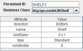
Shelves have the following attributes:
- direction
- name
- slot sizes
- type
- x slot index
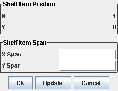
The slot sizes attribute has a dedicated editor associated with it which you can display by clicking the attribute value in the attributes table. This attribute includes the number of slots and their horizontal and vertical sizes as illustrated in the following figure:
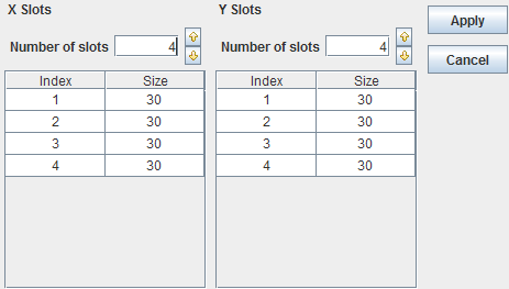
In this editor, you can change the number of slots along the x and y axes of the shelf, either by clicking the up and down arrows at the right side of the corresponding fields, or by typing an integer in the fields. The number of slots you specify determines the number of rows in the tables of the editor. In both tables, you may change the size of each slot individually.
When you remove slots, their sizes are saved. If you subsequently add slots, the saved slot sizes will be applied in the first place. Once all the saved sizes have been reused, the last saved size will be applied to any additional slot.
Card Carriers
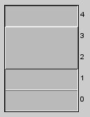
Card carriers are resizable objects which can be inserted in shelves and card carriers. They contain slots in which you can place cards. The slots all have the same size. This size depends on the number of slots and the overall size of the card carrier.
Card carriers have the following attributes:
- direction
- name
- slot count
- type
You can edit the spanning of a card carrier, that is, the space over which the card carrier extends. In the buffer view, right-click the card carrier to display a pop-up menu with the command Span Editing. This command displays the following dialog:
This dialog allows you to change the spanning of the card carrier over the x and y axes. For example, if you specify an X Span of 0.3 and a Y Span of 2, you get the following result:
Cards
Cards are resizable objects that can be inserted in shelves and card carriers. They can carry ports and LEDs. If this is the case, the ports and LEDs are positioned relative to the origin of the card. These objects keep their position when the card is resized and thus may be drawn outside of the card. They remain part of the card, though.
Cards have the following attributes:
- direction
- name
- type
Like a card carrier, you can edit the spanning of a card by right-clicking the card in the buffer view. For more information, see Card Carriers.
Ports
Ports are nonresizable objects that can be inserted in cards. They have the following attributes:
- direction
- name
- type
LEDs
LEDs can be inserted in cards. They have the following attributes:
- direction
- name
- type
- width
- height
Palettes
You can perform several operations on the Equipment Editor palettes.
Importing a new palette
To import a new palette, choose Import a New Palette from the Palette menu.
- Select an XML file that describes an equipment or a set of objects.
- Click Import.
A new palette is added to the existing set of palettes. The name of the palette displayed in the editor is the name of the XML file without the extension. If a palette with the same name already exists, a unique number is added to the name of the palette.
Renaming a palette
To rename a palette, choose Rename Palettes from the Palette menu.
- Select the palette to be renamed.
- Click Rename. (The name of the palette must be unique).
- Click OK to confirm your changes or Cancel to abort them.
Adding or removing a palette
To add or remove a palette, choose Organize Palettes from the Palette menu.
- To add a palette, type the name of the new palette in the text field and click the button Add. The name of the palettes must be unique.
- To remove a palette, select it in the list, and click the button Remove.
Click OK to confirm your changes or Cancel to abort them.
Adding new objects to a palette
You can add objects from the active buffer view to any palette, except to the default palettes:
- Click the palette in which you want to add objects.
- Select one or several objects in the buffer view.
- Choose Add Objects from the Palette menu.
Removing an object from a palette
You can remove objects from a palette, except from the default palettes:
- Click the palette from which you want to remove objects.
- Select the objects in the palette.
- Choose Remove Objects from the Palette menu.
If you have an object made up of several base items and you want to keep a lower level item, drag and drop this object in the buffer view, then add it to a palette as explained in Adding new objects to a palette. Finally, remove the higher level object in the palette.
In the case of a complex object, you have to click at the very edge of the top-level object to select it.
Saving palettes
When you quit the application, the user-defined palettes are saved in XML format. The name of the XML file is the name you gave to the palette when you added it or when you renamed it, followed by the .xml extension.
By default, the user-defined palettes are saved to data/palettes. The editor uses the resource file userPalettes.ini to save the list of user-defined palettes. The name of this file is given by the property equipmentEditor.palette.user.resources that you can modify in the file resources/properties/EquipmentEditorConfig.properties. Note that the editor uses the property equipmentEditor.palette.path to find the resource file, which must be in the same directory as the XML file that describes the palettes.
The path to save the default palettes is given by the property equipmentEditor.palette.default.resources that you can modify in the file resources/properties/EquipmentEditorConfig.properties.
Background
You can place a background behind the equipment you are designing in the buffer view. The supported formats for a background file are: jpg, png, and ivl.
A background cannot be selected nor edited.
Removing a Background
To remove a background, select Remove Background from the Background menu.
Customization
The paths to the labels and icons used by the editor can be customized through a property file located in resources/properties/EquipmentEditorMessages.properties.
You can modify the property file to use your own labels and icons.
When several persons use the same installation, it is recommended that you override the property file with a customized copy named <username>.properties that should be put in the directory resources/properties. This is mainly to avoid conflicts when using customized palettes.
For example, if your username is jsmith, you should create:
- a subdirectory named
jsmithin the directorydata/palettesto store your own palettes. - a file named
jsmith.propertiesin the directoryresources/properties, containing at least the following property:equipmentEditor.palette.path = data/palettes/jsmith
This saves your palettes in data/palettes/jsmith and avoids conflicts with other users.
Equipment Files
The editor uses a specific format (.eqt) to save the equipment displayed in a buffer view. In fact, when you save a buffer view, four files are created:
- A
.eqtfile, which is used as a tag to load the equipment and its configuration. It contains information like the creation date and the path to the equipment and configuration files. - A
.xmlfile, which contains the description of the equipment. The name of the file is<name_of_the_eqt_file>_template.xml. - A
.cssfile, which contains the description of the configuration of the equipment, such as the presence of a background. The name of the file is<name_of_the_eqt_file>_config.css. - An image file, which contains the preview of the equipment to be displayed in the future when the user asks to load this equipment configuration file.
You can also load and save .xml files describing equipment. When you save such a file, you will be asked if you want to save it as an XML file (you will lose configuration information such as the background) or to create an Equipment Editor file (.eqt).
Installation Directory
The Equipment Component - Editor sample is installed here.
Classes Involved
-
ilog.tgo.IltSystem
The class that initializes a JViews TGO application.
-
ilog.tgo.datasource.IltDefaultDataSource
The default datasource implementation.
-
ilog.cpl.IlpEquipment
The equipment component.
-
ilog.cpl.IlpTree
The tree component.
-
ilog.cpl.equipment.renderer.IlpBackgroundsRenderer
This class gives control over the backgrounds of an IlpEquipmentView.
-
ilog.tgo.model.IltShelf
This predefined business object that represents shelf configurations.
-
ilog.tgo.model.IltCardCarrier
This predefined business object that represents card carrier configurations.
-
ilog.tgo.model.IltCard
This predefined business object that represents cards that can compose shelves or card carriers.
-
ilog.tgo.model.IltPort
This predefined business object that represents ports that can compose a card.
-
ilog.tgo.model.IltLed
This predefined business object that represents LEDs that can compose a card.
Source Files
-
equipmenteditor.EquipmentEditor
The entry point of the sample.