Creating a basic network component
Shows you how to create a network component to model and represent a telecommunications network. The data for this part of the tutorial is in the file:
To allow the network component to function, you must create a data source to supply the business data in the form of
JViews TGO business objects. See
Data sources.
You can then create a network component and connect it to the data source. See
Creating a network component: a sample.
Next you read in the data from the XML file.
Finally, you add the network component to the container that you defined during initialization. This delimits the physical area in which the network view will be displayed.
This part of the code is referred to as Step 1.
void step1() throws Exception {
1. Create the data source.
mainDataSource = new IltDefaultDataSource();
The data source will contain the business objects used in the application.
JViews TGO supplies
IltDefaultDataSource as a predefined data source. The new instance of
IltDefaultDataSource created here is called
mainDataSource. This data source is not specific to the network component and will be used to supply business objects to other graphic components.
2. Create the network component.
networkComponent=new IlpNetwork();
JViews TGO supplies
IlpNetwork as a predefined network component. The new instance of
IlpNetwork that you create is called
networkComponent.
3. Connect the data source and the network component.
networkComponent.setDataSource(mainDataSource);
Once the data source is set, the network component is notified of any modifications to the business objects contained in the data source. Changes include adding or removing objects, or changing the attribute values or structure of an object.
4. Read the XML file regions.xml containing the network business objects.
mainDataSource.parse("regions.xml");
The data source you have just created reads in an XML file. The method used is
parse.
You can pass as an argument to this method either a filename or a valid org.xml.sax.InputSource that you have previously created.
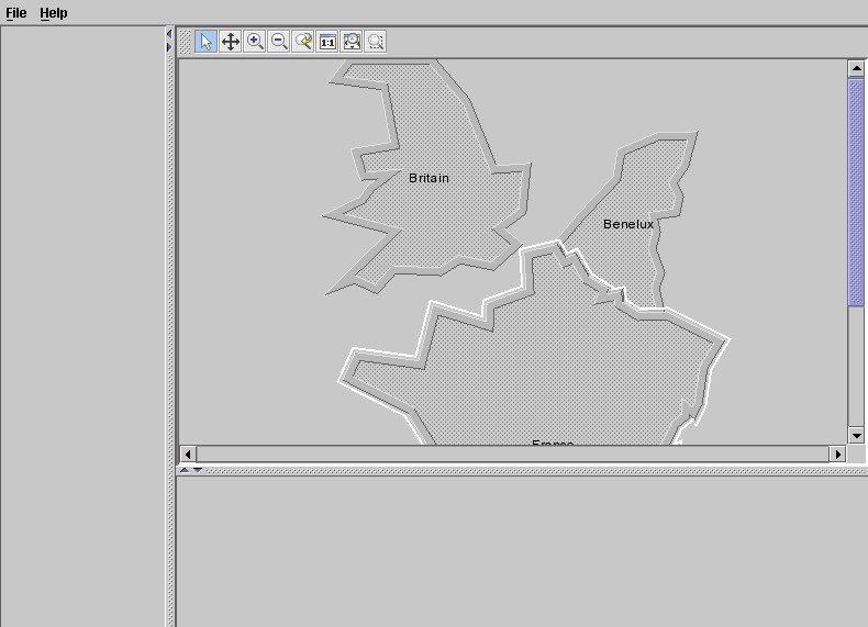
The data in the file adds three business objects,
Britain and
Benelux and
France. They belong to the business object class
IltPolyGroup and have the attributes
name and
position. A position must be an instance of a class that implements
IlpPosition. Here, the type is
IlpPolygon which contains the (x,y) coordinates of the points that define the shape of the region.
For example:
<addObject id="Britain">
<class>ilog.tgo.model.IltPolyGroup</class>
<attribute name="name">Britain</attribute>
<attribute name="position" javaClass="ilog.cpl.graphic.views.IlpPolygon">
<point> <x>167.0</x> <y>106.0</y> </point>
<point> <x>160.0</x> <y>84.0</y> </point>
<point> <x>196.0</x> <y>78.0</y> </point>
<point> <x>186.0</x> <y>24.0</y> </point>
<point> <x>142.0</x> <y>18.0</y> </point>
...
<point> <x>191.0</x> <y>104.0</y> </point>
</attribute>
</addObject>
Note that all the data in an
JViews TGO XML file must be defined in the element
<cplData>. See
Data sources.
5. Add the network component to the container or frame.
networkArea.add(networkComponent, BorderLayout.CENTER);
}
This code causes the network component to be displayed in the corresponding area of the main frame.
The network component should look as shown in the following figure.
Copyright © 2018, Rogue Wave Software, Inc. All Rights Reserved.
