REMEZ Function
Designs an optimal linear phase FIR digital filter using the Remez exchange algorithm.
Usage
result = REMEZ(nfilt, ftype, edge, fx, wtx[, lgrid][, iters])
Input Parameters
nfilt—(scalar) The filter length.
ftype—(scalar) The type of filter. Set ftype to 1 for multiple passband/stopband, 2 for differentiator, 3 for Hilbert transformer.
edge—A one-dimensional floating point array specifying the upper and lower cutoff frequencies, up to a maximum of ten bands.
fx—One-dimensional floating point array of length N_ELEMENTS(edge)/2 containing the desired frequency response in each band.
wtx—One-dimensional floating point array of length N_ELEMENTS(edge)/2 containing the positive weight function for each band.
lgrid—(optional) A scalar value to set grid density. (Default: lgrid = 16)
iters—(optional) A scalar number between 1 and 25 indicating the maximum number of iterations within the REMEZ exchange algorithm. (Default: iters = 25)
Output Parameters
iters—(optional) The number of iterations within the REMEZ exchange algorithm. On output, iters is a scalar value containing the actual number of iterations used.
Returned Value
result—A filter structure containing the impulse response of the optimal filter.
Keywords
None.
Discussion
Given a desired magnitude response:
F(ejq )
this function uses Parks’ and McClellan’s variation of the Remez exchange algorithm to find a linear phase FIR filter:
H(ejq ) , such that
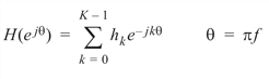
which approximates the desired magnitude response.
The approximation criteria is to minimize the weighted Chebyshev error given by:
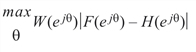
where W(ejq) is a positive weight function.
The specific implementation of this function is based on the algorithm in McClellan, Parks, and Rabiner, 1979. This numerical implementation utilizes samples of the functions F(ejq) and W(ejq) given by:
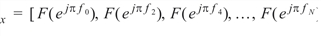 and
and
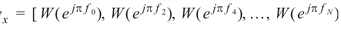
as the input arguments for the frequencies specified by:
edge = [f0, f1, ..., f2N]
The frequency points must be between 0 and 1, where 1 is the Nyquist frequency. The frequencies must have increasing order.
The value of  and
and  defines the desired magnitude response and weight function for the interval (fk, fk+1) for k = 0, 2, 4, .... The values of the magnitude response and weight function for the intervals (fk, fk+1) for k = 1, 3, 5, ... are undefined and are so-called “don’t care” regions.
If ftype = 1, REMEZ designs Type 1 and Type 2 linear phase FIR filters when nfilt is odd or even, respectively. (See FIRLS for the four types of linear phase filters.)
If ftype = 3, REMEZ designs Type 3 and Type 4 linear phase FIR filters when nfilt is odd or even, respectively.
If ftype = 2, REMEZ also designs Type 3 and Type 4 linear phase FIR filters when nfilt is odd or even, respectively, but the values of fx and wx are treated differently. The values of fx(k) specify the slope of the desired frequency response:

on the interval (fk, fk+1) and the values of wx(k) specify the weight function evaluated as:

In the solution, the values of  and
and  are interpolated onto a dense grid of points proportional to lgrid * nfilt/2. The default value of lgrid is 16.
The linear phase filter coefficients are returned in a filter structure:
where m = nfilt – 1.
Example
In this example, REMEZ is used to compute a multiband filter. The results are shown in Log Magnitude Response of Multiban Filter.
nfilt = 55
ftype = 1
edge = [.00, .10, .20, .30, .36, .50, .60, .72, .82, 1.00]
fx = [0, 1., 0, 1., 0]
wtx = [10.0, 1., 3., 1., 20.]
h = REMEZ(nfilt, ftype, edge, fx, wtx)
; Plot the filter response.
PLOT, FINDGEN(512)/511, ALOG(ABS(FREQRESP_Z(h))), XStyle = 1, $
Title = 'Log magnitude response of multiband filter'
OPLOT, [0, 1], [0, 0], COLOR = .5*!D.N_Colors
OPLOT, FINDGEN(512)/511, ALOG(ABS(FREQRESP_Z(h)))
For Additional Information
McClellan, Parks, Rabiner, 1979. Oppenheim and Schafer, 1989 section 7.6.


